Canadian Dollar (CAD)
 Euro (EUR)

E-Maxx Spur Gear Replacement Instructions
NOTE: These instructions are for first-generation E-Maxx
Replace spur gear
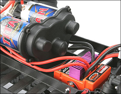
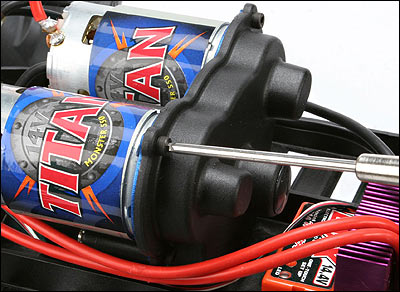
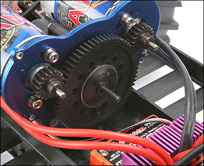
1. Detach the motor wires from the gear cover, and then remove the four 3x4cap head machine screws that secure the gear cover to the motor plate. Next,remove the gear cover from the motor plate to access the spur gear.
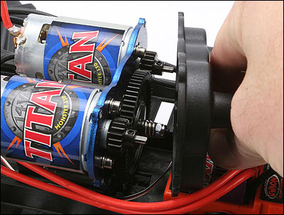
2. Secure the spur gear (using side pressure) with your fingers, and thenthread the slipper nut off of the slipper shaft completely. Slide the slipperspring off of the slipper shaft.
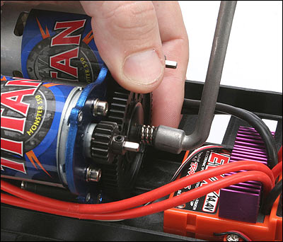
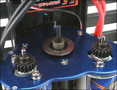
3. Remove the outer pressure plate and slipper ring from the slipper shaft,followed by the spur gear. The metal spur gear bushing may come off with thespur gear. Make sure to leave the metal spur gear bushing on the slippershaft.

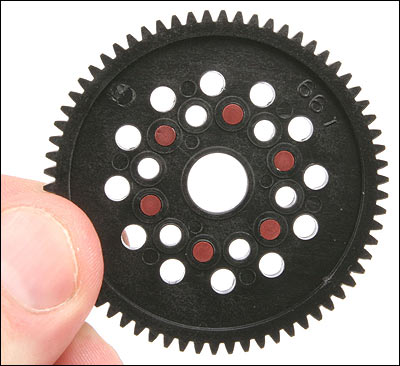
4. Install six new friction pegs.
5. Check both of the slipper rings for excessive wear, and replace them ifnecessary. Make sure that the notch of the inner slipper ring is keyed-in withthe pin on the pressure plate. Tip: Standing the E-Maxx up onto its frontbumper will aid in keeping the slipper ring keyed into the pressure plate.
6. Next, Make sure that the metal spur gear bushing is located on theslipper shaft, and then install the new spur gear (with friction pegs) onto theslipper shaft. The bushing should fit into the center hole of the spurgear.
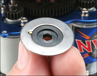
7. Note the key pin on the outer slipper plate. Place the outer slipper ringonto the pressure plate keying the notch in the ring with the pin in the plate.Tip: Use a drop of CA (tire glue) to keep the slipper ring attached to thepressure plate during this process.
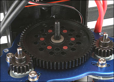
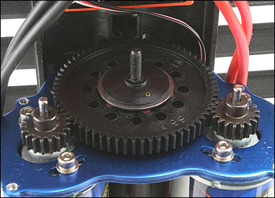
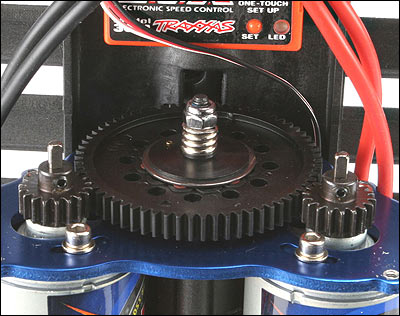
8. Slide the pressure plate and the slipper ring assembly onto the slippershaft and up against the spur gear. Follow the pressure plate with the slipperspring, and then thread the slipper nut onto the slipper shaft. Tighten theslipper nut until the spring is stacked (collapsed). This will be a good basesetting. Loosen the two 3x10 caphead motor screws (just slightly) to adjusteach motor for proper gear mesh, and then tighten each screw once the correctmesh is set.
TIP: Position the gears as close together as possiblewithout binding. There should be a slight amount of play (lash) between thepinion gears and the spur gear.
9. Install the gear cover back onto the motor plate and secure it with thefour 3x4 cap head machine screws.