
 Canadian Dollar (CAD)
 Euro (EUR)

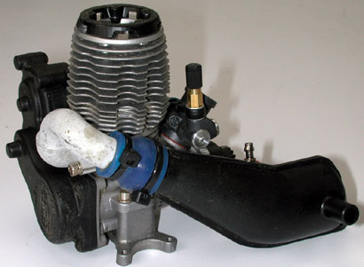
TRX Racing Engine
Rebuild Instructions
The instructions below are for the rebuilding of the Traxxas TRX 2.5, 2.5R, and3.3 Racing Engine once the engine and EZ-Start® system have been removedfrom the chassis. Before you remove your engine for a rebuild, consider tradingit in for a new engine using the Power-Up Program. Rebuildingengines from parts can be costly and time consuming, and can be outside themechanical skills of many enthusiasts. With the Power-Up Program, a worn out ordamaged engine can be traded in for a brand-new, factory-fresh TRX® RacingEngine right away by simply exchanging your worn engine at your local hobbystore. The cost is 1/2 of the retail price of the new replacement engine.It’s less expensive than rebuilding the engine yourself and you get thepeace of mind knowing your engine is brand new (not refurbished), and ready todeliver the power and reliability you expect. In many cases, installing the newengine only takes minutes and you're back in action.
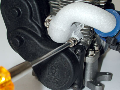
1. Start by removing exhaust pipe and header from the engine by removing thetwo 3x15CS screws.
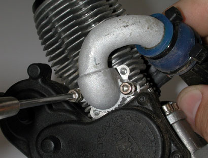
Remove the three 3x12BCS screws that secure theEZ-Start® assembly to the engine and separate the gear housing from theengine.
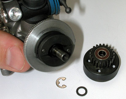
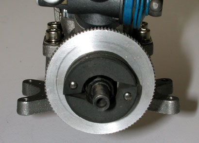
2. Remove the 5.0 E-clip from the crankshaft andslide the 5x8x0.5TW with the clutch bell off the crankshaft.Caution: it's important to use eye protection when removingthe E-clip from the shaft to prevent the clip from causing an injury. Pull theclutch shoes off the flywheel pins.
Remove the flywheel nut from the crankshaftusing an 8mm socket and disconnect the flywheel from the crankshaft by lightlytapping the back of the flywheel with a rubber or plastic mallet. Place a smallflat blade screwdriver into the slot of the split cone washer and twistslightly to loosen the split cone from the crankshaft. Slide the split conewasher off of the crankshaft.
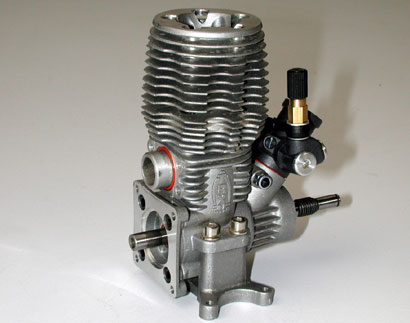
The engine is now ready to be rebuilt.
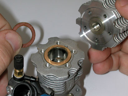
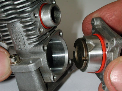
3. Remove the glow plug from the cooling headand discard the plug. The glow plug should be replaced with a new one any timethe engine is rebuilt. Remove the four 3x6CS screws from the back plate of theengine and pull the back plate from the crankcase.
Remove the cooling head from the engine case byremoving the five 3x12CS head bolts. Be careful not to lose or damage thecopper head gasket. If the head gasket is damaged, replace with a new one.
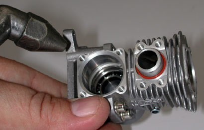
4. Locate the bottom of the sleeve through therear opening of the crankcase. Press the bottom of the sleeve upward with aplastic or wooden stick.
This is to prevent internal damage to thecrankcase. The sleeve should slide up and out of the crankcase.Note: If the sleeve does not slide out of the crankcase withreasonable effort, slightly warm the crankcase with a hair dryer to about 130F. Do Not use an open flame to warm the engine!
The sleeve should slide easily at thistemperature.
Use gloves to protect against burns. Rotate thecrank to where the rod and piston is located at TDC (top dead center). Gentlypull on the bottom of the connecting rod with needle nose pliers, sliding therod off of the crank pin. Be careful not to damage the connecting rod if therod is being reused.
The rod and piston assembly will exit the top ofthe crankcase.
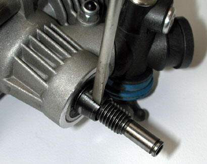
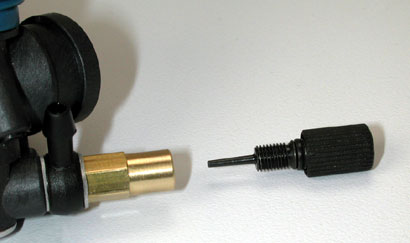
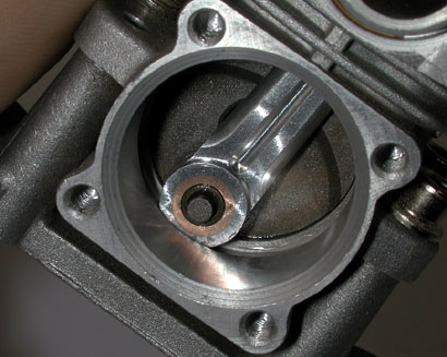
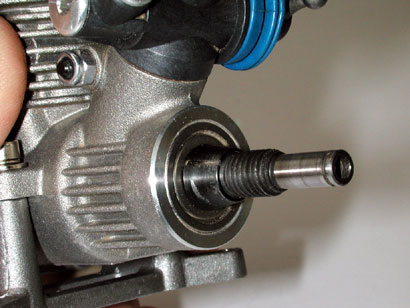
5. Push the end of the pilot shaft through thecrankcase.
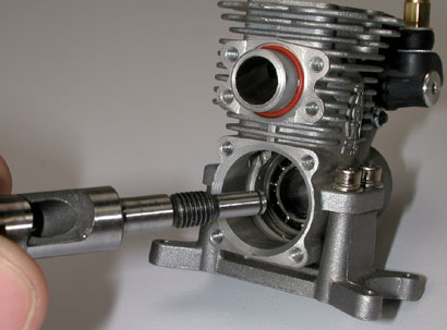
The crankshaft should exit the rear of thecrankcase. Loosen the 3.0NL just below the base of the carburetor. Slide thecarburetor up and out of the crankcase. Now the crankcase is ready to beflushed clean and inspected.
6. Flush the crankcase and bearings out withdenatured alcohol or electric motor spray. Dry the crankcase out withcompressed air. Caution: Always use eye protection when using compressed air.Inspect the crankcase and bearings for damage or missing parts.
Make sure that the bearing cages are not brokenand check for corrosion inside of the crankcase. The bearings should feelsmooth and have little play. Inspect the exhaust O-ring gasket and the backplate O-ring gasket for tears. Replace these O-rings if needed.Note: Never use engine sealant or RTV on a TRXengine. They are precisely engineered to use special O'rings fora proper seal.
7. Apply a few drops of 'Mobil 1' syntheticmotor oil to the bearings. Inspect the crankshaft for corrosion and also checkfor scratches or score marks around the intake port of the crankshaft. Checkthe crank pin for wear. The connecting rod should fit and rotate smoothly onthe crank with no play between the rod and the crank pin. If there is playbetween a new connecting rod and the crank pin the crank pin is worn and thecrankshaft will need to be replaced.
IMPORTANT: Do not reuse adamaged or worn crankshaft. This will only cause more problems inside theengine. If there are damaged or worn parts beyond the piston, sleeve andconnecting rod it may be best to take advantage of the ERP program.
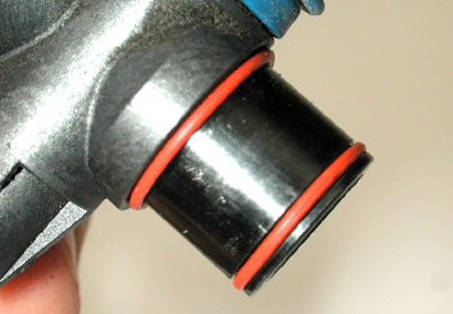
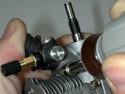
8. Slide the crankshaft back through the crankbearings until it stops. Inspect the carburetor O-rings for damage and therubber throttle arm boot for tears. Note that on carburetors that have a lowerO-ring, it is necessary to replace it when the carb is removed.
Unscrew the high-speed needle all the way out ofthe needle housing and flush out the high-speed needle housing and thecarburetor body with denatured alcohol or electric motor spray.
Use compressed air to dry the components.Reinstall the high-speed needle into the needle housing and return the mixturesetting back to the factory recommended break-in setting (four turns out fromfully closed). Carefully insert the carburetor into the crankcase until fullyseated. While pressing the carburetor firmly into the crankcase, tighten thepinch bolt. This process ensures that the upper O-ring forms a good sealbetween the carburetor and the crankcase.
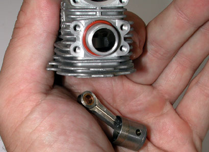
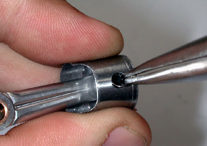
9. Apply a drop of oil in the piston's wrist pinbore before installing the wrist pin. Locate the oiler hole in the connectingrod and the skirt relief side of the new piston. Insert the connecting rod intothe piston with the piston skirt relief and the oiler hole on the same side asshown. Line up the wrist pin bore in the rod with the wrist pin bore in thepiston and slide the wrist pin through the larger opening of the piston. Notethat the closed end of the wrist pin should be inserted first. The orientationof the wrist pin is to help keep wrist pin cooler.
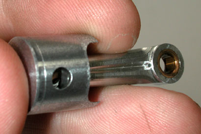
Install the wrist pin clip (G clip) into thegroove of the wrist pin bore of the piston. This will retain the wrist pininside of the piston. Be sure to fully seat the G clip in the groove inthe piston!
Lower the piston and connecting rod assemblyinto the top of the engine case with the oiler hole of the connecting rodfacing toward the crankshaft. Apply a drop of oil onto the crank pin beforeinstalling the connecting rod onto the crank pin. Slide the connecting rod overthe crank pin and rotate the crank pin to the bottom center of thecrankcase.
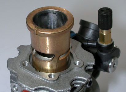
10. Lube the outside of the piston and slide thenew sleeve into the engine case. Make sure the piston fits into the sleevewithout binding. Press the sleeve all the way down into the engine case.Important: The slot (in the lip) at the back of the sleeve must key into thepin at the back of the engine case opening. Do not install the cooling headuntil these two items are keyed into each other.
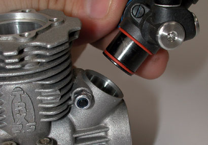
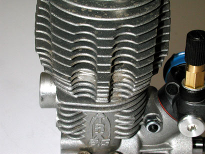
Place the copper head gasket onto the sleeve andset the cooling head into the sleeve. Note that there are two slots notchedthrough the cooling fins on each side of the cylinder head. These slots are foraccess to the engine mounting screws.
The five head bolts should line up with the fiveholes on top of the engine case and the access slots on the cooling head shouldline up with the slots manufactured into the engine case.
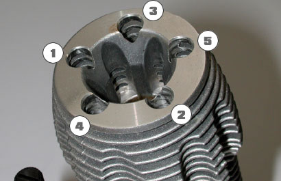
Be careful not to damage the copper head gasket(see picture for orientation). While pressing the head squarely onto thesleeve, thread the head bolts into the engine case just until they stop. Do nottighten down these bolts individually. It is very important to attain evenpressure around the cooling head. Slowly tighten each screw just a little at atime in a crossing pattern, (see picture) until each bolt becomes snug. Finisheach bolt in the same pattern with 9.7in/lbs of torque.
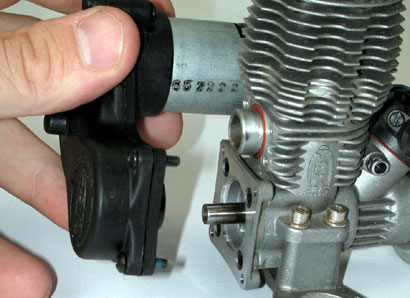
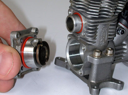
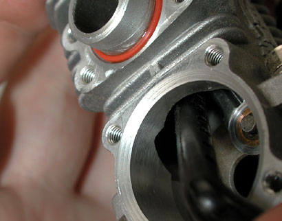
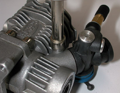
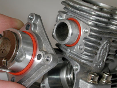
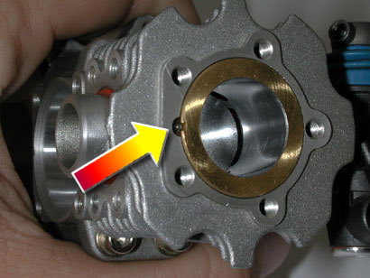
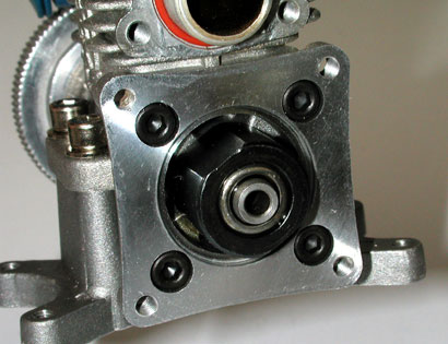
11. Connect the back plate with the startershaft to the engine case. Important: The reliefs that are manufactured into theback plate must face up to match the ports inside of the engine case (seepicture for orientation).
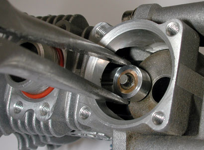
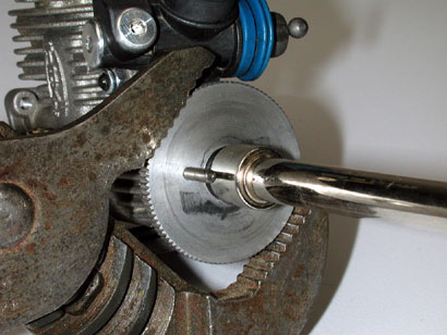
Key the starter shaft to the crank pin by slowlyrotating the starter shaft as pressure is applied towards the crankshaft.
Once the starter shaft is keyed into the crankpin, join the back plate to the engine case and secure the assembly with thefour 3x6CS screws. Install a new glow plug (#3232 is recommended for the TRX2.5 Racing Engine, and 3232X for the 3.3) into the cooling head. The engine isnow rebuilt and ready for the installation of the clutch assembly and theEZ-Start® system.
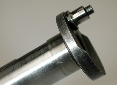
12. Slide the split cone washer over the pilotshaft with the larger opening toward the engine case.
Slide the flywheel over the pilot shaft and joinit up with the split cone washer. The split cone washer should fit inside ofthe tapered hole in the flywheel. Thread the flywheel nut all the way up to theflywheel and tighten the flywheel with 62.0 in-lbs. of torque against theflywheel.
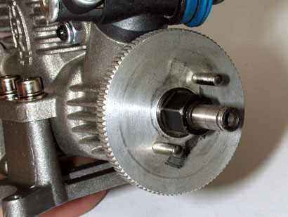
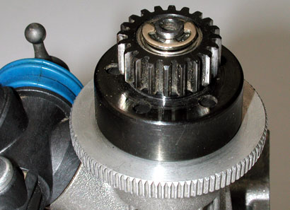
13. Slide the clutch shoes onto the flywheel.Key the flywheel pins into the holes of the clutch shoes (See picture fororientation of the clutch shoes).
Racer Tip: Byreversing the direction of the clutch shoes, the clutch shoes will provide alittle firmer bite against the interior wall of the clutch bell. This is usefulon higher bite surfaces that offer a higher level of traction.
14. Clean and lube both clutch bell bearings andinstall a ball bearing into each side the clutch bell and slide the clutch bellover the pilot shaft followed by the 5x8x0.5TW. Fasten the 5.0 E-clip (wearingsafety glasses) around the pilot shaft to retain the clutch assembly.
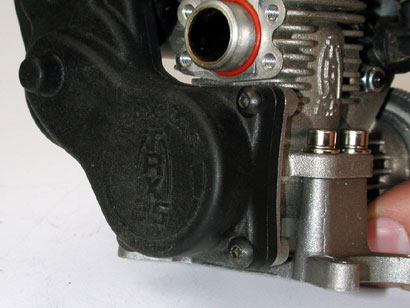
15. Clean the roller clutch with denatured alcohol and lube the rollerclutch with Mobil 1 synthetic motor oil. Slide the EZ-Start® system (withthe roller clutch) onto the starter shaft that exits the back plate of theengine. Note that the roller clutch is to be installed onto the starter shaftso that the clutch engages the starter shaft clockwise and rotates freelycounter-clockwise.
Note that the engraved text on roller clutchfaces the engine backplate for correct rotation. Fasten the EZ-Start® gearcase to the back plate with the three 3x12BCS screws.
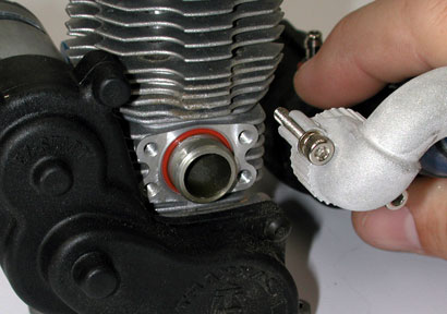
16. Mount the exhaust header and pipe assemblyback onto the rear of the engine case. With the two 3x15CS screws.
The engine, clutch, exhaust system andEZ-Start® assembly is now ready for installation into the chassis.
NOTE: Newly rebuilt enginesrequire break-in.
Break-in instructions are located in the owners manuals (TRX 2.5/R orTRX3.3).