
 Canadian Dollar (CAD)
 Euro (EUR)
Learn How Shock Placement Affects Your Suspension Setup
Tuning with Lower Shock Position
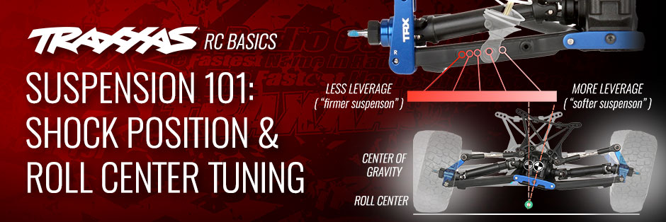
 Each corner of the suspension system represents a lever, load, and fulcrum.
 Changing the lower shock position alters how much leverage the arm has on the shock.
Tuning with Upper Shock Position
 Note how the shock “stands up” relative to the arm as the suspension is compressed.
Moving the top of the shock outboard (away from the chassis) will create maximum rate change between full extension and full compression. Moving the shock inboard will reduce the change in rate. Greater rate change can improve cornering on high-grip tracks, and improve control in rough conditions. Less rate change can improve traction in loose conditions and allow more responsive suspension action. As with all suspension tuning, the setting is a compromise and only testing can reveal the best choice for your terrain conditions and your driving style.
 Changing the shock’s top position alters how much the effective spring and damping rate changes as the shock is compressed.
Understanding Roll Center
The geometry of the suspension system’s arms and camber links creates a virtual point around which the chassis rolls—that’s “roll” as in “rotates around the X axis.” This point is called the roll center. The distance between the model’s roll center and its center of gravity (CG) effects how the model transfers weight when cornering.
 When we talk about the “roll” in roll center, we’re referring to rotation around an axis through the center of the model from front to rear.
Roll center is revealed by extending the suspension arm and camber link planes until they intersect, then drawing a line from the center of the tire’s contact patch to the intersection. The point where tire line crosses the centerline of the chassis is the roll center. Because roll center is determined by the geometry of the suspension arms and camber links and these are moving components, roll center is dynamic and changes with suspension movement.
 Extending the arm and camber link planes and intersecting them with the tire’s contact patch reveals the roll center, which is below the chassis and its center of gravity.
When your model corners, inertia makes the chassis roll toward the outside of the turn. The chassis rolls because its CG is higher than the roll center. The distance between the roll center and the CG determines how resistant the chassis is to rolling. Lowering the roll center will increase the distance between the CG and roll center, which results in more chassis roll and increased cornering traction; raising roll center will reduce chassis roll and lessen cornering traction.
 The distance between the CG and roll center represents a lever that pushes the chassis to the outside of the turn. Raising the roll center shortens this virtual lever. A shorter lever means less leverage and less chassis roll (and vice-versa).
 Front and rear roll center do not have to match. The Slash 4X4 Ultimate’s front roll center is lower than the rear’s, which would give it more front grip (or less rear grip—it’s all relative).
That marks the end of the third installment. Click on the links below to see other installments of our Suspension Tuning Guide series
- Click here to see part 1: Camber & Toe-In
- Click here to see part 2: Shock Absorbers
- Click here to see part 4: Sway Bars and Tuning Tips